
- Scan Our WeChat QR Code to Add Me to Your Contacts for Chat


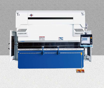
Electro-hydraulic servo CNC press brake has a frame structure with an all-steel integral welding design. By annealing to eliminate internal stress, it ensures the overall precision of the machine tool. With excellent rigidity, it offers exceptional resistance to distortion and tilt. The thickened worktable plate and slider enhance the machine rigidity significantly. Thus, in bending, both the slider and worktable have minimal deformation, ensuring outstanding straightness and angle consistency of the workpiece.
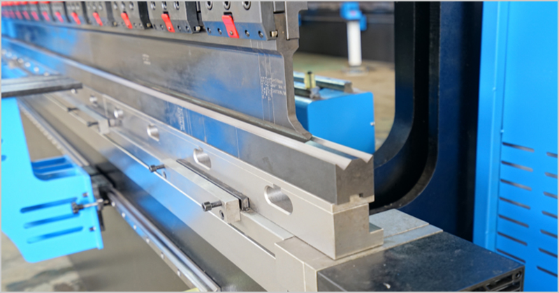
Capable of bending various metals and pliable acrylic materials, offering a diverse range of specifications and configurations tailored to meet customer requirements, including bending length and thickness.
Reliably process a variety of materials, including high-strength plates like aluminum plates, stainless steel such as 201 and 304, brass, manganese steel pipes, T700 and T1000.
High precision, surpassing the precision of standard CNC bending machines by 60%.
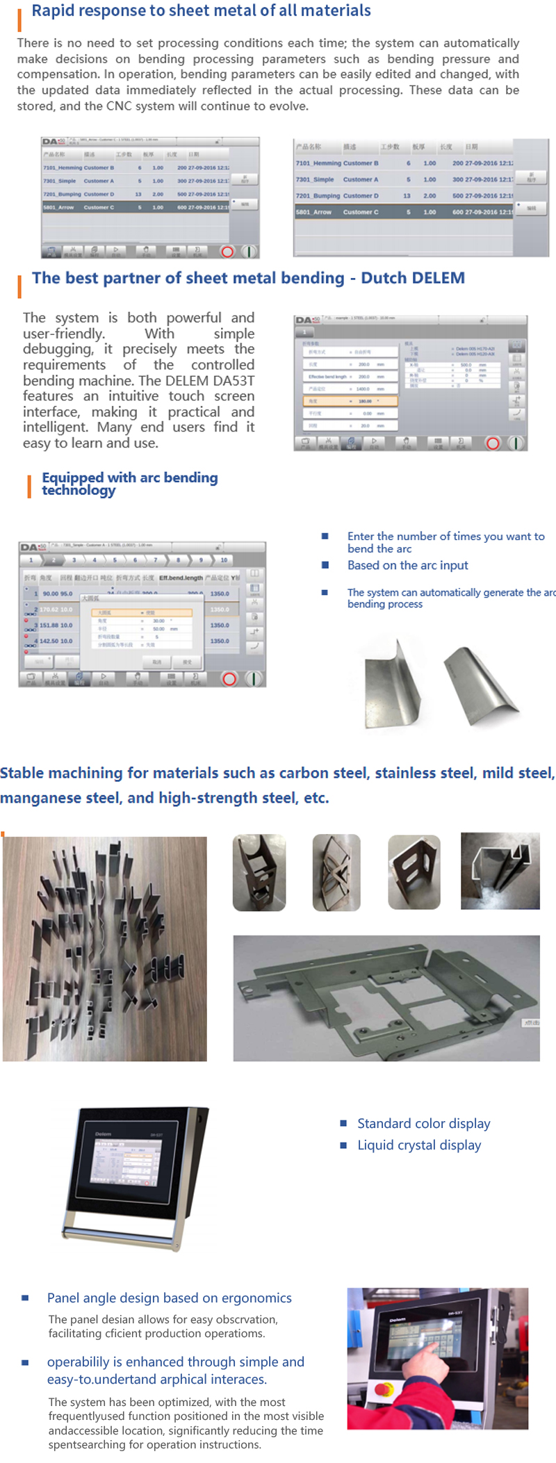
With its imported intelligent system, the machine can autonomously calculate the required bending pressure, taking into account factors such as plate thickness, material type, and length. Moreover, it has the capability to automatically generate arc bending programs.
The standard 4+1 axis model notably reduces the reliance on manual expertise and lessens workload, thus having enhanced work efficiency.
The system offers flexibility as different systems and modules can be replaced to align with specific customer requirements.
Optional configurations such as 6+1 axes and 8+1 axes are also available.
The mechanical structure of this machine tool primarily consists of the frame, worktable, slider, main oil cylinder, and back gauge. With refined design and manufacturing processes, it effectively ensures the precision of both manufacturing and operational use of the machine tool.
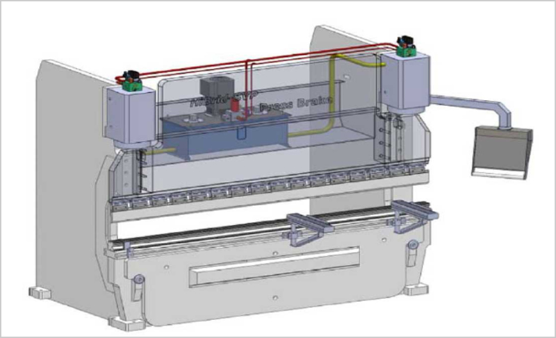
The cylinder is forged as a single part, while the piston rod undergoes triple chrome plating and mirror surface treatment, providing effective wear resistance and precision. This makes it a simple and stable structure.
1. Complete seal sets from Japan's NOK are employed to minimize the risk of oil leakage.
2. Using electro-hydraulic servo technology not only ensures high precision but also enhances response speed.
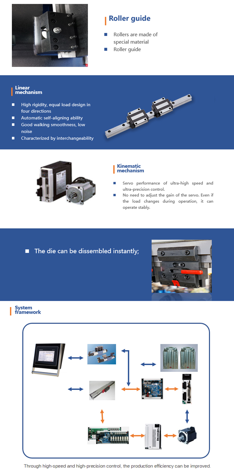
3. Introducing the original roller-type four-point guide rail technology, which, unlike other similar products, eliminates the risk of guide rail separation. This significantly improves the safety, stability, and processing precision of the machine. Compared to rack transmission technology of the same level, the service life is increased by at least five times.
Performance Index
Slider speed | 180mm/s | |
Location precision of back gauge | ± 0. 05mm | |
Slider positioning precision | ± 0. 05mm | |
Confirguration
Control system | 1 set | DELEM DA53T | |
Double-joint movable boom | 1 set | Self-manufactured | |
Liftable crossbeam | 1 set | Double linear guide | |
Main motor | 1 set | Wannan Motor | |
Linear guide, screw | 2 set | Taiwan Taiwin | |
Hydraulic system | 1 set | Germany Rexroth | |
Gear pump | 1 pc | USA FIRST | |
Joint | 1 set | EMB | |
Sealing ring | 1 set | Japan NOK | |
Grating ruler | 2 pcs | Italy GIVI | |
Main control electrical | 1 set | Schneider | |
Compensating mechanism | 1 set | Automatic mechanical compensation | |
What Makes It Special
▲ Using a large floor boring and milling machine, employing the integral one-time processing method for precise operations to ensure the overall processing precision.
▲ Using the Dutch DELEM DA53T system to manage the Y axis (i.e., the vertical movement of the slider).
▲ Displaying the current and target positions of X, Y, and V axes.
▲ Offering manual, semi-automatic, and fully automatic operation modes.
▲ Incorporating specialized software to enable timely processing of various graphics and characters, ensuring ease of use.
▲ Equipping the back gauge device with automatic material backoff and delayed action.
▲ Employing high-performance servo motors, precision ball screws, and linear guide rails for the back gauge device, ensuring reliable positioning precision and repeatable precision for the X-axis transmission.
▲ Using a mechanical tie rod deflection compensation table with advanced European technology to ensure workpiece processing precision. This system is automatically calculated and adjusted by the CNC system, which selects the deflection compensation amount based on material properties and notch size, and is controlled and adjusted automatically by the CNC system.
▲ Offering low operating costs to meet the demands of 24-hour industrial production.
- The die undergoes post-casting processing, ensuring high precision and excellent strength.
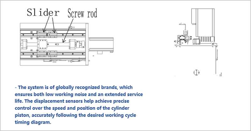
- Screw drive ensures high precision and stability, with a double slider design for enhanced performance.
- To maintain machine precision and stability during operation, the back gauge is made in a screw rod drive mode, ensuring precise operation.
Dual guide rails are employed to enhance machine stability and minimize fluctuations.
- The compact design facilitates easier installation, and the oil pump can be conveniently disassembled and assembled.
-Finite element analysis is used to achieve optimal rigidity and weight.
-Rigorous stress detection is made for the machine through software-based finite element analysis during the design process, ensuring that the machine meets load requirements while operating and enhancing structural refinement and design rationality.
Machine tool type | WF67K-100T/3200 | |
Nominal force | 1000kn | |
Bending length | 3200mm | |
Distance between posts | 2750mm | |
Cylinder stroke | 200mm | |
Slider speed | Fast down speed | 180mm/s |
Return speed | 130mm/s | |
Working speed | 9mm/s | |
Motion precision of slider | Positioning precision | ±0. 05mm |
Repeated positioning precision | ±0. 05mm | |
Maximum opening height | 490mm | |
Depth of inlet | 400mm | |
Main motor | Power | 7.5KW |
Rotational speed | 1400r/min | |
Pressure | Wannan | |
Workpiece precision; | Straightness | 0.2mm/m |
Angle | ±30dec/m | |
Numerical control system | Dutch DELEM DA53T | |
Number of control axes | 4+1 (Y1, Y2, X, R, + V) | |
Back gauge | Stroke | 500mm |
Velocity | 200mm/s | |
Positioning precision | ±0. 05mm | |
Repeated positioning precision | ±0. 05mm | |